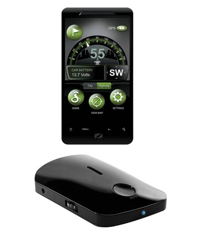
#Cobra irad 500 Bluetooth#
This IC is designed to reduce the part count that is needed when implementing a Bluetooth radio. At the heart of the Bluetooth module is a CSR BC417143B Bluetooth SOC. One of the unique features of this particular radar detector is the in the inclusion of a Bluetooth module to send data to a smartphone equipped with the iRadar app. Additionally, a third regular smaller regulator is used create a 3.3v rail.
#Cobra irad 500 series#
The device uses two 7800 series linear voltage regulators to generate a 5v and an 8v rail. Power Supplyĭue to the radar detector's application of being always plugged in, the device employs several linear regulators to achieve the voltage supply rails that the electronics inside need to function. The radar horn assembly connects to the main board through a 2x4 header pin. These circuit boards were de-soldered and can be seen in the image below.īoth circuit boards in the radar horn. The two circuit boards are connected to each other through 4 pins that were soldered into place. This secondary circuit board amplifies and processes the signal detected by the receiver. The secondary board on the bottom of the radar hornĪttached to the bottom of the radar horn is another circuit board. Additionally, this circuit board is made with a special substrate intended for RF applications. This board contains the Superheterodyne receiver that is used to detect 3 bands of radar X band (8 to 12GHz), K band (18 to 27GHz) and Ka band (27 to 40Ghz). This circuit board contains gold traces as opposed to the typical copper ones. After taking out even more screws, the radar horn comes apart into two sections revealing a circuit board. The radar horn is used to direct radar waves to the detection circuitry.

The big star of any radar detector is its wave guide or ‘radar horn’. The bottom of the main circuit board Radar Horn An interesting observation is that the female header, that can be seen by the ARM microcontroller, protrudes from the bottom of the plastic enclosure and is then covered by the FCC ID label. On the bottom of the electronics, a the main microcontroller can be seen. The electronic components came out in a very nice module that can be seen below.

It didn’t take much to open up this radar detector, I removed four Phillips screws and it was open. Inside of this radar detector's relatively simple package, there are a lot of electronics! For example, there are 4 separate circuit boards, around 25 screws, and +10 IC’s. When this radar detector originally came out its MSRP was $130. In this Teardown Tuesday, we're going to take a look inside of a radar detector! We are going to look at a Cobra iRad 500, this radar detector is unique in the fact that is designed to pair with a cell phone's Bluetooth connection and have the phone display various alerts as opposed to a display on the device.


 0 kommentar(er)
